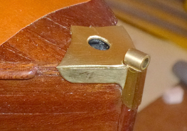
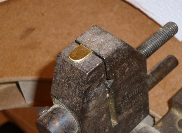
| 1) TRANSOM BRACKETS These fit on the corners between the transom and the sides, and hold the stays for the torpedo launching rails. They are the easiest of the brass fittings to make, so this is a good time to practice your skill. Trace from the plan, cut out from 1mm brass sheet and bend to the exact angle to fit on the hull. Also make the rudder mounting bracket now (see below) as it's made in the same way. Note: Brass sheet can be surprisingly hard because it's made by rolling. It can be softened (annealed) by heating to red heat with a blowlamp. |
 |
|
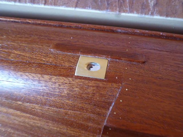
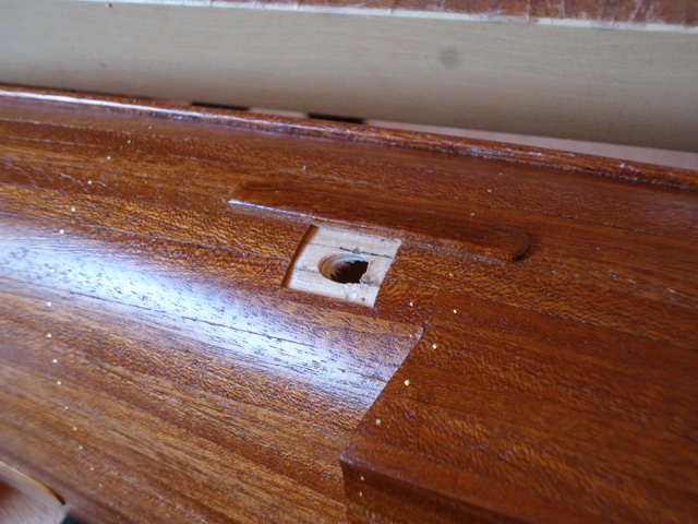
2) EXHAUST SURROUNDS The plan shows these to be oval, but I used the squarer shape from later CMBs because it's much easier to make and looks equally good. Cut rectangles of suitable size from 1mm brass sheet and drill/file an angled hole in the middle for the exhaust pipes. The hull is curved, so bend the brass over a suitable former until the curvature matches. Holding the brass in position, carefully mark around the outside, then cut through and remove the secondary planking to provide a recess for the brass. |
|
|
3) NOSE FITTING This looks complex, but can be broken down into relatively simple shapes. The top and sides are cut from 1mm brass sheet, the front is brass channel and the 'tube' is two concentric sections of brass tube. With no experience of soldering with a flame, and deciding this was not the time to try it, all metal parts are fitted with superglue. |
|
|
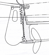
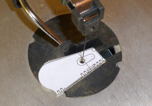
4) RUDDER & RUDDER SUPPORT This photo shows how useful it is to cut the part from the plan and stick it to the brass as a template. Here, a scroll saw is used to cut the rudder as accurately as possible from 2mm brass sheet. Finishing is done with files and then wet and dry paper. The rudder fits into another section of 2mm brass, the rudder support (the shaded area below), which is made in the same way.
To fit the rudder assembly, first superglue the rudder mounting bracket to the hull. Then glue the rudder to the rudder support, and fit a small piece of brass rod to represent the hinge. Finally superglue the rudder/rudder support assembly carefully onto the mounting bracket. Check that the alignment is perfect. Tilting the boat at this angle means that gravity holds it in place while the glue sets.
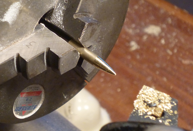
At the bottom of the rudder support is what I call the 'bullet', which holds the end of the propshaft. This is turned from brass rod, and a hole for the propshaft drilled in the other end.
|
|
|
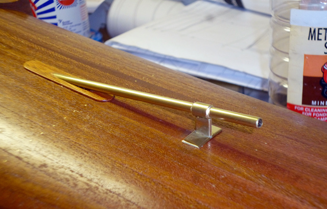
5) PROPSHAFT MOUNT This is actually six pieces of brass. The propshaft surround is two concentric lengths of brass tube, as is the collar around it. The 'T' bracket is two pieces cut from brass sheet, and the whole thing carefully assembled with superglue. The propshaft surround doesn't go through the hull as it appears, but instead is acutely angled to match the hull, and the join covered by a section of 10mm sapele.
|
 |
|
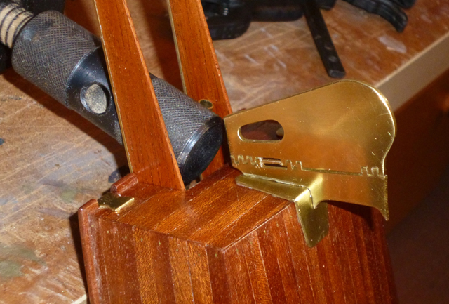
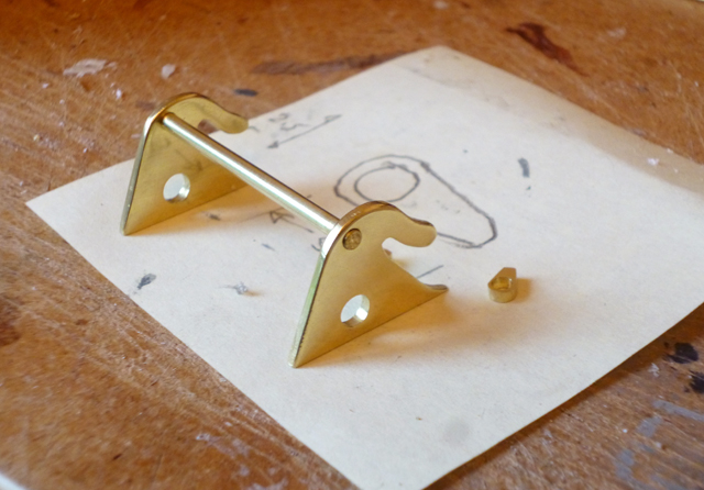
6) LIFTING BRACKETS CMBs had lifting brackets at front and rear so they could be hoisted aboard ships. The forward brackets were under the oval deck hatch and so invisible, but the rear brackets must be made. They also incorporate the torpedo release mechanism. Like the rudder, they are cut from 2mm brass sheet, drilled and hand finished. From the port bracket via a pivoting link, a long brass bar connects to the torpedo firing lever (see next page).
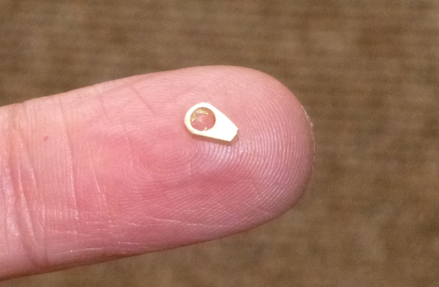
These two tiny levers fit onto the rod between the two lifting brackets, and shafts (not shown) extend downwards to engage behind the rear lugs on the torpedo. With parts this small I found it easier to drill the hole first, then complete the shape around it. The whole torpedo release mechanism is faithfully copied from the plans. Take time to understand the mechanical sense because you'll need to replicate it. See it completed here.
|
|
|
|