|
7) OILER This relatively simple feature which is fixed to the transom is turned from 10mm brass rod, and a hole drilled in the bottom for the oil tube (brass wire) which will run down to the rudder.
|
 |
|
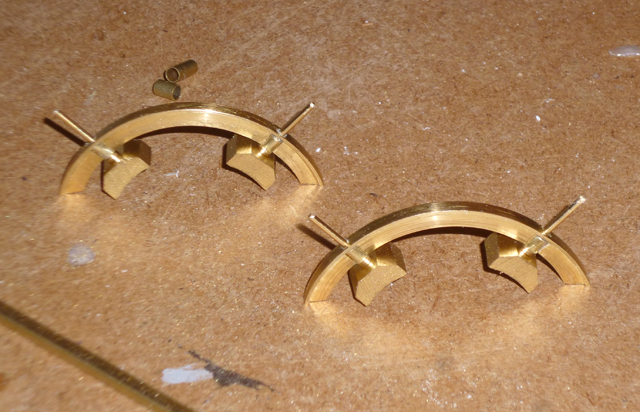
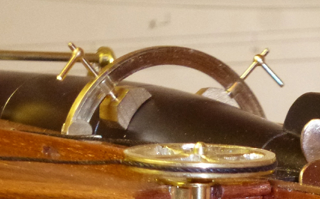
8) TORPEDO TROUGH ARCHES These were some of the hardest parts to make. The two rearmost arches are the same size and T-profile, and can be cut from one ring. A disk is cut from 3mm brass sheet, drilled centrally so it can be fitted into the chuck with a bolt, and the outer edge turned true. Then the jaws are reversed and the inner aperture turned. Note: On my plans the cross section showing the rear arch was a slightly bigger scale than the rest, so check this before proceeding. The front arch is made in a similar way, but is smaller with an inverted T-profile. A disk is cut from 3mm brass sheet, the inner aperture turned, then the outside machined as required.
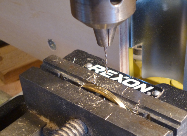
The holes for the torpedo clamps are carefully drilled.
The structures are completed with clamps that go through the arches to hold the torpedo. Photos of the real CMB at Duxford were useful reference. Cuts are made inside the arches under the holes, and short lengths of brass tube superglued in place. The small blocks are made from plastic and sprayed gold. The rods are cut-down stanchions left over from another model, and small handles (the tops of the same stanchions) will be fitted to the tops of each.
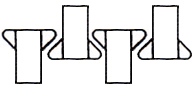
The ends of the arches fit to the deck via short pieces of C-channel and small metal plates. The latter are not visible here but I made a special same-size template to act as a cutting guide (below).
|
|
|
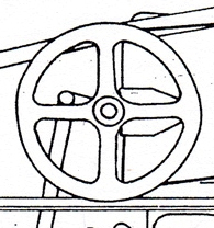
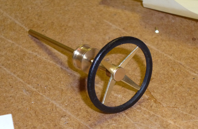
9) STEERING WHEEL This is made from six pieces. The steering column is brass rod, and the steering drum is turned from 10mm brass rod. The 'spokes' are actually a single piece of brass sheet, cut and filed into a + shape. The bosses above and below it are turned brass rod, the lower one drilled to take the shaft. The rim is turned from black formica and fixed with superglue. |
 |
|
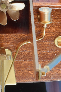
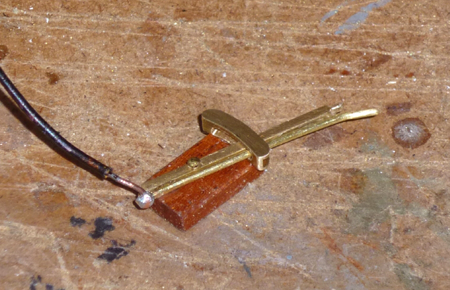
10) TORPEDO FIRING LEVER The lever is made from brass strip and brass wire - note the little protuberance on the former for a tiny handle to be added later. The slot is brass C-channel curved to suit, with a slot drilled and filed through for the lever. Black wire is soldered to to the bottom to represent the firing cable, and the assembly glued to a small piece of mahogany. A pin represents the pivot. |
 |
|
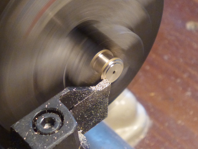
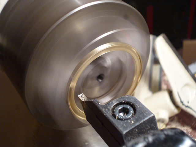
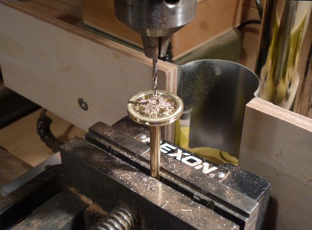
11) RUDDER WHEEL I found this to be the hardest fitting of all. A disk is cut from 3mm brass sheet, then turned true on a lathe where the outer groove is also made (this will take the rudder cable later). Then four quadrants have to be drilled, cut out and filed to leave four spokes.
|
 |
|
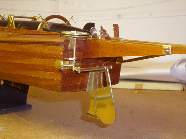
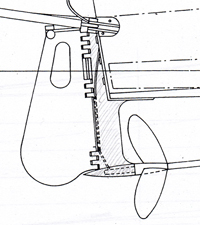
12) RUDDER LINKAGE This complex structure is assembled from lengths of brass I-channel joined with short sections of brass rod to simulate hinges. Again, the real CMB at Duxford was very useful. You can also see the brass tips on the end of the launching rails, made from a small brass piece with brass C-channel on top. The tops of the rails are clad with thin brass strip.
The linkage completed. Now you can fit the launching rail stays (not shown here) which fit between the brackets on the transom and the end of the rails. They are easy to make from brass tube with brass rods set into each end. See here for the final look. The final part is the rudder cable. Cut two short lengths of narrow brass tube, grind a very acute angle on the forward ends, and glue the correct length of black thread between them. Loop the thread around the rudder wheel and superglue the brass tubes to the deck. |
|
|
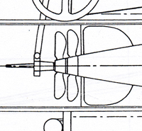
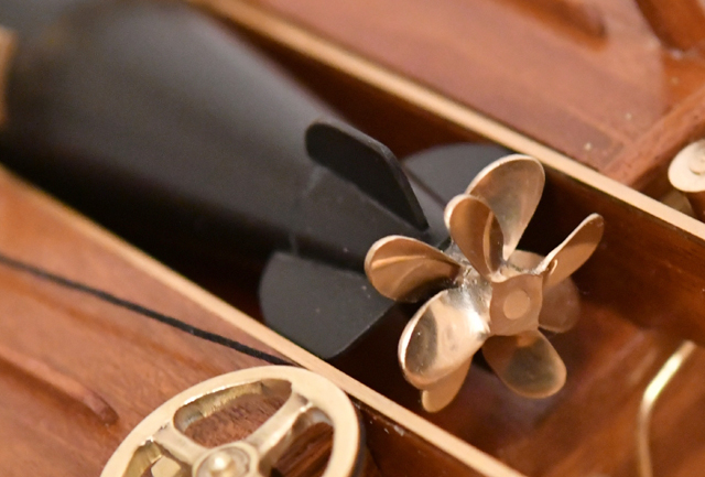
13) PROPELLERS The propellers (one for the boat and two for the torpedo) had to be cast, but as this was well beyond my knowledge, they were the only part of the model to be subcontracted. I used The Prop Shop, who make excellent propellers, but be prepared for a long wait. This is a photo from the completed model showing the contra-rotating torpedo propellers These were stock items, so I ground the blades narrower for better authenticity, and made the rear prop slightly smaller in diameter. They are fitted to the torpedo with a piece of brass rod to act as a propshaft.
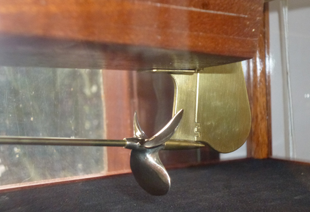
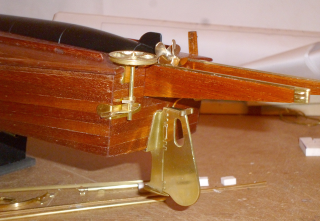
The boat's distinctive propeller was cast especially. It slides onto the propshaft which is then fitted between the propshaft sleeve and the 'bullet' under the rudder support.
|
|
| Other minor fittings not detailed here: Large front cleat (hand made from 3mm brass sheet), air pipe ends (brass eyelets), small side cleats and klaxon (stock items sprayed gold), brass flag base (stock item), towing post (mahogany and brass wire), mast (2mm dowel), rigging, White Ensign. | |
|
|
|