|
Before you start... You will need: Somewhere to work, bandsaw, disk sander, lathe, scroll saw, bench drill, orbital sander, miniature drill, kettle for steaming, files, craft knife, straight-edge, pins, ruler, sandpaper, wet and dry paper, PVA glue, superglue. Materials: Plywood - 2mm, 4mm and 9mm. 1/16" mahogany sheet. Sapele - 6x1mm, 10x1mm, 3x3mm and 3x2mm. Brass - 1mm, 2mm and 3mm sheet, brass tube and rod of various sizes, brass C-channel and I-channel. You can get most of it from these very helpful suppliers: Cornwall Model Boats, Hobbies
|
|
CMB INSTRUCTIONS 1 Framework |
| The hull
is based on a central keel with formers fitted at right
angles. These are
taken directly from the plans (1:16 scale). 1) FORMERS Scan and mirror the former profiles to produce complete cross-sections, like the ones shown here. Alternatively you could print the profiles shown here but check the size is correct - the maximum width is 162mm. You'll need five copies of this diagram, one for each of the front formers F1-5... |
.jpg) |
| ...and six copies of this
diagram for the six rear formers (F5a-10). F10 is the transom. F5 is where the step in the hull is, so there are two hull profiles and therefore two formers here. I called the rearward one (without the lower corners) F5a. Mark a line 2mm in from the edges all round to allow for the thickness of the planking. Stick templates F1-9 onto 4mm ply, and F10 onto 9mm ply. Cut them all out, ideally with a bandsaw, and then make the curves perfect with a disk sander. |
.jpg) |
|
2) KEEL
Cut out a keel template from the centre drawing on the plans, and mark a line 2mm in from the edge all round to allow for the thickness of the planking. Stick it onto 9mm ply and cut it out.
Now modify the parts as follows:
Formers: a) Make slots for the keel.
b) Make cut-outs in F7-10 for the torpedo trough, allowing an extra 1.5mm for the side and base panels which are fitted later.
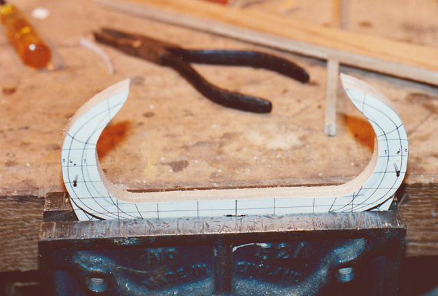
c) Cut out the top and middle of formers F5, F5a and F6 to make the cockpit space. These formers will support the floor (see below) so check with the plans to get the final floor height correct.
F5 and F5a are glued together (see photo on right). F5 provides the bearing for the front planks, F5a for the rear planks.
Keel: a) Make slots for formers.
b) Make a cut-out for the cockpit (across F5 and 6) and the torpedo trough (F7-10).
c) Bevel each side of the front (stem) to allow for planking. |
.jpg)
|
|
3) BASIC ASSEMBLY Test fit the formers onto the keel, adjust if required, then glue in place with PVA glue, ensuring everything is square and the keel straight. |
.jpg) |
|
4) COCKPIT FLOOR Make four small strips from 4mm ply and glue them onto the relevant faces of F4 and F7. They will support the ends of the floor so take care to get the height exactly right. Make the cockpit floor (2 halves) from 4mm ply or hardboard, cut slots to accommodate the formers F5 and F6, and glue in place. Fill any gaps between the floor and the formers.
This photo of the underside shows clearly how the step in he hull is created by formers F5 and F5a. |
.jpg)
|
|
5) PROW QUADRANTS Make prow quadrant templates from the plan, stick to 4mm ply sheet, cut and fit. |
.JPG) |
|
6) BOW BLOCKS
Fill beneath the quadrants with balsa blocks and carve/sand to shape, observing the contours from the plan.
File the edges of the keel and all formers to the correct angle ready for planking. Check that the planks will sit naturally over all the curves.
|
.JPG)
|
|
|
|
.jpg)
.JPG)
.JPG)